 Go Home
Site Map
Servicing GM Direct Ignition System
Warning: DIS coils generate considerably more power than many stock distributor based ignition systems. DIS ignition can kill you. Do not touch DIS components or sparkplug wires with the engine running.
DIS here means DIS2 is GM system design and not number of coils. Same system is used by V6 and V8 but uses a different CPS setup. Some GM documents have DIS2 but most only DIS. If you see old cars with DIS then most engines have DIS2.
The DIS Brick is far more reliable than distributor-based ignition however there are 2 costs to this reliability. The first is that the parts are expensive and the second is that it appears more complicated than it is which scares allot of people off.
Scaring people off is likely a good thing in light of the first cost. DIS parts add up really fast. The PIM alone is $120+ if you fry it. Then add coils at $30-50 each. If you also manage to damage the ECM then add another couple hundred dollars. As you can see the last thing you want to do is replace DIS parts unless they are truly bad.
The truth is that DIS is very simple. The Fiero DIS "brick" consists of 5 main parts. 2 coils, the PIM(Primary Ignition Module), the mounting plate, and the Crank Position Sensor which is hidden under the mounting plate. There are no adjustments at all as the PIM and the ECM control the whole system. Parts in DIS systems mostly work or they don't. (Ancillary parts include 2 screws 4 carriage bolts with nuts and the PIM shield.)
How DIS works.
In very short form.
The only moving part in DIS is the crankshaft notch wheel. The crank position sensor generates pulses as the cuts in the notch wheel pass by it.
The ECM and PIM control Spark timing based on pulses from the crank position sensor and a number of other factors. (Proper operation of the MAP sensor is critical. The ECM uses the MAP sensor to calculate Vacuum Advance for the spark amongst other things.)
Coil selection is done by the PIM based on the input from the crank position sensor.
Spark plugs are wired in series to fire in pairs. One plug of the pair is in the cylinder under compression and the other is in a spent cylinder under exhaust.
Note that on all DIS2 setups; One plug on each coil fires "backwards," meaning spark goes from ground to tip. Some DIS setups look similar but all plugs fire as normal, spark goes from tip to ground.
DIS Brick
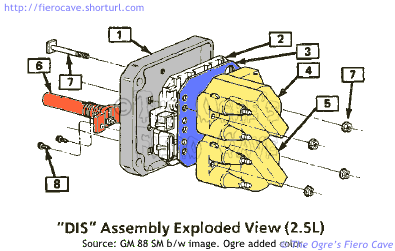
- Base Plate
- Module
- Shield
- 2/3 Coil
- 1/4 Coil
- Crank Sensor
- Studs and nuts to mount Module and Coils (Torque: 40 Lbs In, 4.5 N-m)
- Screws to mount Crank Sensor (Torque: 20 Lbs In, 2.3 N-m)
Not showed:
Seals between Module and Coils. (Orange in color.)
Three Bolts to mount DIS assembly on Block. (Torque: 20 Lbs Ft, 20 N-m)
Source: GM 1988 Service Manual
DIS Wiring
| Definition of terminals available on the Primary Ignition Module | ||
|---|---|---|
| Connector/Terminal | Wire color | Function |
| C1/A | White | Tachometer Feed, Output to Dash |
| C1/B | None | Not used |
| C1/C | White | EST, Output From ECM |
| C1/D | Tan/Black | Bypass control, Output from ECM |
| C1/E | Purple/White | Reference Pulse, Input to ECM |
| C1/F | Black/Red | Ground, ECM reference |
| C2/A | Black/White | Ground, Frame (Block) |
| C2/B | Pink | Key on Bat+, Fused |
|
Coil Primary terminals: Top & Bottom (outer) connect
to terminal C2/B. Middle terminals are firing control, switched to ground. |
||
As mounted on the cast iron 2.5l engine, Terminal A is the bottom terminal on each connector.
Firing Order: 1-4-2-3 counted from bottom most secondary terminal.
Exact firing order doesn't matter as long as the sparkplugs are paired on the correct coil. 1 & 4 must be on the bottom coil while 2 & 3 must be on the top coil.
Code 42 EST error & Grounds
Any time you see DTC 42, Electronic Spark Timing, check both the ground wires for the ignition module very carefully. If either are damaged this error is one of the possible results.
- The reference ground runs to the ECM. Check the harness between the engine and firewall for damage. If the exhaust was ever cracked/leaking then this section of harness may have damage.
- Power Ground running to the engine is for the module and coil to give you spark voltage. Depending on the setup, the main ground runs to a bolt on the bell housing or the stud bolt on the brick. (Most Fiero use the trans bell housing bolt near the DIS Brick.)
Is the PIM shield missing? Can cause Code 42 error!
Once you eliminate grounds etc first then may need a PROM update. See 87-88 DIS Duke ECM.
The PIM shield plate
When the shield is missing, you can damage the PIM simply by installing the coils. The seals around the coil terminals are designed to seal thru the thickness of the shield. Without the shield the seals are over compressed and can cause so much pressure the PIM actually fractures.
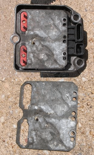 At first glance you'd think the galvanized steel shield on top of the PIM was
part of it. Since it is stuck on tight enough to stay in place by itself
that first impression gets reinforced.
The fact is that the shield IS NOT part of the PIM and needs to be transferred to any new PIM installed in the brick. DO NOT discard it. The shield is not included with new PIMs! If the plate is lost you may have problems with the ignition. The only places to get a replacement are your local Pontiac/GM dealer or a scrap yard.
The shield provides magnetic shielding for the PIM. The coils build and break dense magnetic fields and can generate stray signals in surrounding parts. There maybe thermal protection for the coils or PIM but it not the main function.
Keep in mind that when you heat the coils the internal resistance rises as well. This means the coils will lose power. They can lose so much power the car will die until they cool down. At the very least you loose spark energy and end up with reduced performance and gas mileage.
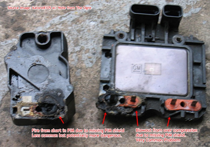
One last thing... See the orange seal pieces on the coil connection? They will seal Thru the shield to the Coils. When the PIM doesn't has the shield over compressing of the seal will cause a blowout in the PIM. No shield can cause a short or even a fire. Like this... (Click on image if you want it bigger.)
Make a Shield?
Made from Sheet Steel with Galvanize. I think its 19 gauge...
My only shield is in my car... And I'm not pulling it to measure directly... Measure gap I get 0.046... This page says 19 gauge in sheet w/ galvanized.
Likely can use 18-20 ga sheet w/ Galvanized... seal has some give... maybe use dielectric grease w/ 18 to be sure
DIS Sensors
MAT
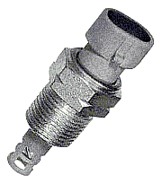 The Manifold Air Temperature sensor, also listed as Air Charge
Temperature sensor in many parts books, is located to the right of the TBI in
the intake manifold. It is an uncoated NTC Thermistor exposed directly to manifold
air. NTC, Negative Temperature Coefficient, means the resistance drops as
temperature rises.
This sensor is used mainly to fine tune the fuel air mix. If it's covered in carbon or cooked by engine backfire, it can cause strange problems and may or may not set ECM codes.
Problems with this sensor often show up during idle. At idle the air moves slower and has time to heat up as it passes thru the intake plumbing. The sensor is more sensitive to error as the temperature increases.
Carbon build up or cooking can alter the sensor resistance by a few ohms. At low temperature, a few ohms of error are a small percentage of the sensor resistance. However as temperature rises, the percentage of error increases as the sensor resistance drops.
| Intake Air Temperature |
Normal MAT Resistance |
Error | % Error |
|---|---|---|---|
| low | 3500 Ohms | 20 Ohms | 0.57 |
| high | 150 Ohms | 20 Ohms | 13.33 |
What this means is that when intake air temp is up around 130-150F, common during idle, the sensor is lying to the ECM. The ECM adjusts the fuel mix based on this and if the lie is big enough you'll get 44 or 45 errors.
To make this even more annoying, the ECM error may only show up under certain weather conditions. When my 87 did this, the error only occurred when the outside air was very dry. That made it very hard to find the problem since the air in Delaware only gets that dry a few days in the winter.
Even when it wasn't throwing 45 errors it was still affecting fuel economy and performance. This sensor is supposed to be accurate within plus/minus 1 degree C. If we figure the high temperature as 65C(about 150F) then a 20% error is plus/minus 13C(about 30F) of error. This can drive the engine rich or lean depending on if the ECM thinks the air is 30 degrees hotter or cooler than it really is.
Replacement
When you replace the MAT make sure the new one has a plastic cage. You do not want the metal caged one. The metal caged sensor uses a coated Thermistor. The coating will slow the response time of the sensor. You don't want this for a sensor that commonly has to respond to 100 degree temperature changes in a couple seconds.
Why doesn't the V6 have this problem?
The V6 ACT is mounted upstream from the Throttle body and is far less prone to carbon contamination. It's next to impossible to cook it. The location also runs cooler so that when there is an error it has less effect on the signal to the ECM.
The V6 also uses a coated sensor. The coating isn't a problem for the V6 because the air temperature doesn't change as much or as fast where it's located.
MAP
The MAP, Manifold Absolute Pressure, sensor is used for both fuel mixture and ignition timing. It is also used briefly during startup to measure the local barometric pressure, which helps the engine compensate for altitude and weather. If this sensor is batty you will have trouble and it often will not set an error code.
One typical symptom is when you punch the gas and the car backfires or stumbles.
This first thing you have to do is make sure the sensor vacuum line is good. It has to be clean inside, have all joints sealed tightly, and be connected to the correct vacuum port. Even a tiny leak will screw up this sensor.
Keep the vacuum line short so that the MAP sensor will respond instantly to manifold pressure changes. A long vacuum line will take longer to pass the change in pressure to the MAP. This lag can be enough to cause a problem. The exact effect depends on the inside diameter of the line and how long it is.
Don't count on new sensors being good. I've had the stumbling problem and when I did it was a new MAP sensor that caused it. I changed the sensor again, this time to Borg Warner product, and the problem went away.
Map Test
This is a basic test described in many manuals...
Measure voltage of the MAP sensor's output terminal (Center terminal of most GM ones) with ignition on and engine off. Start engine and apply 10 in.(250 mm) Hg to unit, voltage should be 1.2 to 2.3 volts less.
What is Absolute Pressure?
Absolute Pressure means that Zero PSI is referenced to an Absolute Vacuum, instead of Atmospheric Pressure like your Tire Gauge. Absolute Pressure is used because it simplifies the engine computer and sensors, especially with Turbo/Super charging setups.
- Absolute Pressure is often marked as PSIA, short for "Pounds per Square Inch, Absolute."
- Atmospheric Pressure is about 14.7 PSIA depending on altitude and weather.
CPS
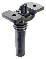 The Crank Position Sensor is pretty reliable. When it does
fail it can be very hard to test.
The problem with testing the sensor is that you can't monitor it while the car is running like you can with other DIS setups. You can try to check it during cranking but that doesn't always help either. The problem may only show up with the engine actually running.
Resistance isn't a reliable test either. The resistance can be perfect but the sensor can still be bad.
If you pull a crank sensor out and find any cracks, other than a little flaking by the tip, then replace the sensor. If the sensor shows signs that something hit it, you need to find out what is happening. There is nothing in the engine that should ever hit the sensor.
Layout of the CPS
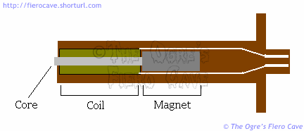
The magnet in the CPS is simply touching the core. There is no other attachment like a weld or adhesive.
Cracking of the CPS shell can damage the coil or create a gap between the magnet and core, effectively killing the sensor.
Replacement
Pack the terminals of the sensor with dielectric compound.
Clean the hole in the block. Make sure there's nothing that will chew up the new O ring.
Oil the block opening and the new O ring before inserting the sensor.
Disassembly
The brick is held to the block by 3 bolts. 2 bolts are 10mm hex heads; the third is a 13mm hex w/ stud. The hex w/ stud at first glance looks like a nut on a stud but it is not.
The coils and PIM are held to the mounting plate by 4 5/16(they are really metric but 5/16 6 point sockets fit just fine) nuts on carriage bolts. Yes. The coils can be removed from the brick on the car but there is a trick to it. Notes on that are farther down this page.
The Crank sensor is on the back of the mounting plate and it held by 2 hex head screws. Carefully inspect the sensor's O-ring for damage as soon as you pull the brick. The sensor hole in the block tends to have rust that will damage the O-ring. If there is oil above the O-ring when you pull the sensor then at the very least the O-ring is bad.
Service & assembly
If the crank position sensor shows any impact damage to the face, consider checking inside of the engine. Nothing should contact the face of the sensor. This is a bit of a judgment call. If the sensor breaks, unlikely but possible, then it can hit the crank and get chewed up. Note: The plastic on the face of the sensor is thin and sometimes flakes off. That won't hurt anything. What we're worried about are signs of impact to the sensor.
If the O ring on the sensor has leaked replace it. This sensor is about 20$us. I really recommend replacing it if the thing it old enough for the O-ring to go bad. When the sensor is replaced you MUST use dielectric grease on the terminals. Pack the grease into the terminals and leave a small blob on the tip of the terminals. This grease MUST be checked and replaced as needed anytime the sensor is separated from the PIM.
The PIM (Primary Ignition Module) and mounting plate must be clean! The mounting plate does not have to shine but it must be free of all dirt, scale, or corrosion. You should apply heat sink compound or dielectric grease to the engine side of the module. This isn't as critical as I used to think but I still recommend it. (GM actually installed these dry.) Besides improved heat transfer, the grease will seal out water. Water of course can cause corrosion that will reduce heat transfer.
Dielectric is available at many auto parts and electrical supply stores. Heat sink compound is available at Radio Shack and most other electronic suppliers. Make a good gob in the center of the PIM and let it spread itself when the PIM and coils are tightened. Allowing the heat sink or dielectric compound to spread itself is important. As the compound spreads it drives out air from between the parts. If we were to try and spread the compound by hand we'd end up with air trapped between the parts. Air doesn't transfer heat as well as the compound so the less air in there the better.
While not required I strongly recommend packing the coil primary terminals with dielectric grease. These are the 2 small holes in the bottom of the coils. These are supposedly weather packed terminals but the extra protection is a really good idea. Also pack the secondary posts where the terminals exit the towers after the coils are tightened.
Tighten the coils and PIM in a star pattern. If you tighten unevenly or over tighten the nuts you could damage the PIM. Go slow to allow the heat sink compound to spread.
Before attaching the brick to the block make sure the crank position sensor hole is clean. It tends to have rust around it that will damage the sensor's O-ring. Oil the O-ring before pushing the sensor in the block. The 3 mounting bolts should be put back where they came from.
WARNING! The TOP bolts penetrate the crankcase and MUST be wrapped with Teflon thread sealing tape prior to installation or you WILL have an oil leak.
You don't have to wrap the whole bolt, just 2-3 turns near the tip. The bolts will be easy to start if you don't wrap the first few threads. The advantage to tape over RTV Silicone is that the tape will seal an oily hole where Silicone may not.
Before connecting the brick to the wiring harness pack the terminals on the harness with a small amount of dielectric. Again this is insurance. The Fiero DIS brick is mounted low. It isn't hard to swamp it in a big rain. Swamping the brick can ruin both the PIM and the ECM. ((Oddly as I was preparing this document, TNN's Shade Tree Mechanic aired a show about a swamped GM that did exactly this. Too weird.))
Servicing coils and PIM without removing brick from car.
It's generally easier to work on the coils and PIM with the brick removed from the car but that creates other problems. The first is that you disturb the crank sensor, which can damage it or its seal. Second is that you unseal the mounting bolts. Both problems can result in oil leaks.
The coils and PIM can be removed with the brick in place but you need to make a small tool to hold the carriage bolt heads. The tool is a 6-inch or longer piece of 1/2 to 3/4 inch wide flat stock. This needs to be pretty stiff and not more than about 1/8 to 1/4 inch thick. It doesn't matter what kind of metal is used. Brass aluminum or steel are all ok. To make the tool bend about 1 1/4 inches of metal 90 degrees. You'll use the bent part to hold the bolts.
To remove a coil, pull up on it as you alternately loosen both nuts. This will keep the bolt heads seated in the mounting plate. Note: If you are only replacing the coils do one coil at a time. This saves you having to reapply heat sink compound to the PIM. ((If the PIM hasn't been off in a long time it doesn't hurt to check it out and clean any crud from around it.))
Once the coils are off check over the PIM as above. Clean the mounting plate as needed, etc, before reseating the PIM. Don't forget to always apply fresh heat sink and dielectric compounds every time the PIM is off.
Only the top left coil bolt is close enough to the block to stay in place by itself. Pull up the other bolts one at a time and reach under the plate with the tool to hold the heads in place. The top right bolt is easiest to reach from the right side of the plate. The lower ones are easiest to reach from the bottom of the plate.
Tighten all 4 coil nuts until they are just touching the coils. Final tighten the nuts slowly in a star pattern. You want to go slow to let the heat sink compound spread. The stuff is thick and spreads slowly. Go around the coil nuts a couple times to make sure they are tight. (They can loosen as the compound spreads after the first pass.)
DIS PROMS
Section moved to 87-88 DIS Duke ECM.
Notes
Unlike HEI the DIS PIM is rather unlikely to die. If you think the PIM is dead always try replacing the crank sensor. The crank sensor is $20 the PIM is $120+. If you do replace a PIM you might as well replace the crank sensor at the same time. ((GM says the crank sensor passing a resistance test of doesn't mean its good. So if you think it's bad just replace it. Almost no-one has the machine to test them fully.))
The main thing to fail in DIS is the coils and that's often because a sparkplug or wire is bad. A damaged plug or wire can fry DIS coils by creating increased current demand on the coils. This increased demand increases heat in the coils. The coils should be replaced in pairs. When coils are replaced you should also replace sparkplugs and wires.
The only test I've found for the coils in GM documents is secondary resistance. (Resistance between towers.) The resistance should be between 5000 and 7000 Ohms. Problem is that even if the coil secondary resistance is ok the coils can still be bad. Mainly you could have a bad primary winding or the insulation could be failing neither of which you can easily test for sure. (Failed insulation doesn't always result in spark leakage that can be seen.) My own testing of the Primary shows about 1 Ohm. At such a low resistance it's hard to tell if it's got a problem other than an open circuit. (The only true test of insulation resistance requires a special machine called a Megger and few people own one.)
DIS uses a 0.060 inch plug gap. Make sure all plugs are as close to this gap as possible. Mismatched plug gaps will unbalance the DIS coils and hurt performance. Unbalanced plug pairs are a good source of rough idle problems and miss. NEVER over gap sparkplugs in DIS systems to prevent fouling. You may prevent fouling but you'll cook the coils. (This huge gap is allot of why many "performance" spark plugs make little or no performance gain.)
The location of the DIS brick on the "Iron Duke" makes it run hot. This has been known to cause problems when aftermarket coils are installed. Aftermarket coils usually draw more current from the PIM resulting in even more heat. This can be enough to push the PIM or coils to failure. The system usually will start working correctly when it cools down but permanent damage can result. Some people have not had this problem, others have. It depends on the exact PIM, the coils, and presence of the PIM shield. There's no way to predict if yours will have problems or not. You'll know if you have this problem when about 8-10 miles after installing the coils the car dies.
The odd bolt-> The stud topped bolt that holds the brick in place is used as a ground point in other cars using this engine. You may safely change this bolt to match the other two. This makes the brick easier to work on since all bolts are now the same. Looks better too.
Aftermarket Parts
Researching aftermarket parts is actually what started this whole page. Problems during that research forced me to find out just how the DIS system operates and how to work on it in much more detail than I wanted.
Lesson #1, stay with standard sparkplugs. Some brands and types of "improved" plugs cause problems with DIS. DIS ignition is already much stronger than traditional distributor ignitions. The benefit of specialty sparkplugs in DIS is minimal if noticeable at all. I was going to test Bosch Platinum plugs but numerous reports of problems using this plug in DIS and the cost of the plugs made me decide it wasn't worth the effort. I did try SplitFire plugs. I found no difference at all in how the car ran vs. new Autolite traditional style resistor plugs.
If you feel you need platinum plugs, stay with Autolite or AC "double platinum" types. These plugs have a platinum pad on the both electrodes. The makers claim this type is designed for use with systems like DIS. The platinum pad on the "ground" electrode effectively gives the plug 2 tips and makes it easier to fire the "backward" plug in each pair. I have used Autolite double platinum without problems. Bosch platinum's have had problems in DIS motors. (Use PFF search in the archives.)
Lesson #2, unless you happen to like yellow allot the DIS coils from Accell are not a very good product. I found them more heat sensitive than OE style coils. The coils also require alteration of the $120+ PIM to fit. The black insert that is supposed to seal the coil primary terminals is likely to fall out while you work which means it also doesn't properly seal the terminals. (Since the black piece was already out I altered the coils instead of the PIM and packed the terminals with Dielectric to prevent moisture problems.) If you are missing the PIM shield then don't even bother with these coils. They will heat up in 10-15 miles and shut down the car. (Hot coils loose efficiency the same way a hot starter does. The internal resistance climbs to where the coils can't properly fire.) This product is not one of Accell's better efforts.
Update... I took the Accell coils off for good. I put OE GM coils back on. Result? I gained MPG and found no performance change. I'll never use the POS Accell DIS coils again.
Lesson #3, you do not need expensive "performance" sparkplug wires on DIS. The system will work perfectly with any brand of high quality wires. I'm using a Borg Warner helical core wire set from Pep Boys on my system. In over 25,000 miles there have been no problems at all with these wires. I forget what they cost. It wasn't very much.
Update... I finally did wear these out. Took about 3 years and 40,000 miles. They are "life time warranted" but Pep Boys are pricks about honoring warranties and wouldn't replace them.
Additional Information
ACDelco has a bunch of technical blurbs on their site. There's a diagram of 4 cyl DIS showing the crank notch wheel. (It's not the exact Fiero system but it will give you the idea.)