 Go Home
Site Map
Headlight Door
Source, all of this page: GM 88 Fiero SM, Page 8A-102-0 thru 8A-102-2.
Wiring Diagram
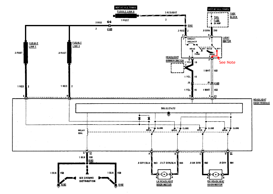
Note: There is a Typo in most diagrams, including 88 Service Manual. Correct wiring showed in Red above. (I've made changes to the diagram to show fuse link C and D gets their power from fuse link B.)
(For a larger image, see here.)
CIRCUIT OPERATION
Voltage to open the Headlight Doors and to power the Solid State circuitry is applied at all times to the Headlight Door Module at terminals B and E of connector CI. With the Light Switch in OFF, voltage to close the Headlight Doors is applied to terminal C of connector CI.
With the Light Switch in HEAD, voltage to energize the Relay coil is applied to terminal A of connector CI.
When the Light Switch is moved to HEAD, voltage is applied to the Headlight Door Motors through the relay contacts in the OPEN position. Ground is provided for the motors through the Solid State circuitry until the Headlight Doors are open.
When the Light Switch is moved to OFF, voltage is reversed across the Headlight Door Motors and the motors run in the opposite direction to close the Headlight Doors. When the Headlight Doors are closed, the Solid State circuitry senses that the motors are not operating and ground is removed.
TROUBLESHOOTING HINTS
Try the following checks before doing the System Check.
1. If the Headlight Doors do not operate, check Fusible Link B and associated, wiring to the light Switch for an open.
2. Check that grounds G101 and G102 are clean and tight.
3. Check Fusible Links C and D for an open.
- Go to System Check for a guide to normal operation.
- Go to System Diagnosis for diagnostic tests.
SYSTEM CHECK
- Use the System Check Table as a guide to normal operation.
- Refer to System Diagnosis for a list of symptoms and diagnostic steps.
System Check Table
|
Action |
Normal Result |
|
Put Light Switch in HEAD |
Headlight Doors open and Headlights on |
|
Put Light Switch in PARK |
Headlights go out; Headlight Doors stay open |
|
Put Light Switch in OFF |
Headlight Doors close |
- Refer to System Diagnosis when a result is not normal.
SYSTEM DIAGNOSIS
- Do the tests listed for your symptom in the Symptom Table below.
- Tests follow the Symptom Table
Symptom Table
A. Neither Headlight Door operates properly
B. LH Headlight Door does not operate properly.
C. RH Headlight Door does not operate properly.
A: NEITHER HEADLIGHT DOOR OPERATES PROPERLY
|
Connect: TEST LAMP At: HEADLIGHT DOOR MODULE CONNECTOR C1 (Disconnected) Condition: · Light Switch: OFF |
|||||||||||||||
|
|||||||||||||||
|
· Light Switch: HEAD |
|||||||||||||||
|
|||||||||||||||
|
· If all results are correct, replace Headlight Door Module. 1. Check Fusible Link C or D and RED (2) wire for an open (see schematic). 2. Check TAIL Fuse, Light Switch, and WHT (103) wire for an open (see schematic). 3. Check BLK (150) wire for an open. 4. Refer to Headlights, Section 8A-100. |
B: LH HEADLIGHT DOOR DOES NOT OPERATE PROPERLY
1. Check for mechanical binding.
2. Remove connector C2 from the Headlight Door Module. (Leave CI connected.) Connect fused jumpers from terminal A (GRY/BLK) of connector C2 to terminal C of the Module, and from terminal B (LT GRY/BLK) of the connector to terminal D of the Module. Operate the Headlights.
- If the LH Headlight Door works, replace the Headlight Door Module.
- If LH Headlight Door does not work, check wiring to the motor. Replace the motor if the wiring is OK.
C: RH HEADLIGHT DOOR DOES NOT OPERATE PROPERLY
1. Check for mechanical binding.
2. Remove connector C2 from the Headlight Door Module. (Leave CI connected.) Connect fused jumpers from terminal C (DK GRN) of connector C2 to terminal A of the Module, and from terminal D (GRY) of the connector to terminal B of the Module. Operate the Headlights.
- If RH Headlight Door works, replace the Headlight Door Module.
- If RH Headlight Door does not work, check wiring to the motor. Replace the motor if the wiring is OK.